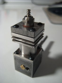
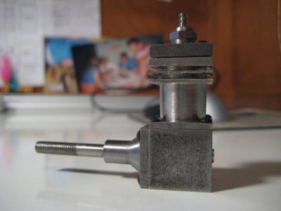
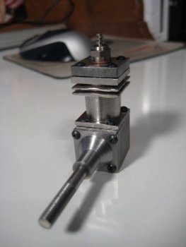
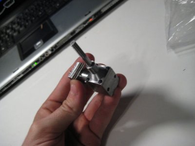
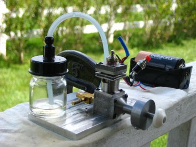
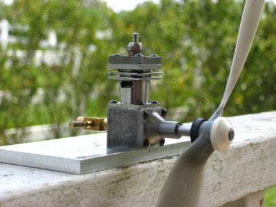
Fresh off the air engine project, we were given the task to design and build something for our second project. I thought the air engine was neat, but a real engine is better. I spent a lot of time designing a two stroke engine which I detail the build of here.
If you want to build it for yourself you can download the plans here.
Cylinder
I decided to go ahead and get the hardest part completed first, so I started with the cylinder. I cut a 1" piece of 3/4" square 1018 Steel bar stock on the band saw.
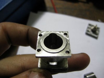
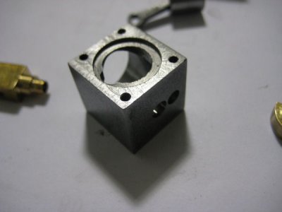
Clamping the piece in the mill, using a 1/2" endmill, I faced off the two ends to make them square and to bring the piece down to length. Next I clamped the piece so that what would be the bottom faced up, this is so that when I bored the hole the very slight spring back of the tool would cause the bottom to be of larger diameter than the top - piston fit near the top of the cylinder is much more critical than near the bottom. Using the edge finder I located to a corner of the piece and counted off to the center (I noted what corner it was so I could locate from the same one when making the crank case for consistency and the help ensure the holes line up). I drilled up to 25/64". Then with the mill boring head and the largest boring bar that would fit the hole, I bored it up to 7/16" using the powerfeed set at the slowest feed to obtain a good finish. This could also be done on a lathe, I chose the mill because I figured the large Bridgeport mill would give a more accurate hole than the rather sloppy smithy lathes, also I like to avoid the four jaw chuck as much as possible. I marked the end I bored from with a sharpie as bottom. At this point I had a rectangular prism with a 7/16" hole bored into it.
The next step is done in the lathe. As much as I avoid using four jaw chuck I had to use one for the next step. Clamp the piece with the bottom facing out, getting the piece centered was a lot easier thanks to the hole I bored in it. I used copper jaws to keep the chuck jaws from marring the part. I cut the .035" step on the bottom them flipped the piece around and cut the .035" step on the top.
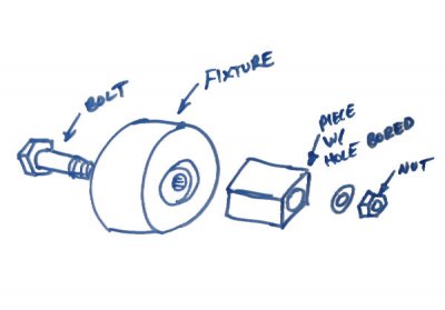
In order to securely hold the part (and keep from using the four jaw chuck) when cutting the fins, I made a fixture that would have a recess to accept the step on the bottom (or top) of the piece, holding the piece securely with a bolt. In the illustration of the fixture below has a bolt and nut, the way mine was made had the bolt threading into a tapped hole in the fixture, eliminating the nut.
Once I had the piece mounted in the fixture, I cut the fins and the area below the fins using a parting tool ground to the correct width. Because of their thinness, my fins got slightly deformed when I cut them. I'm sure there is a way to prevent it, though I have not looked into it.
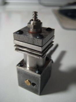
Going back to the mill, I clamped the piece with the bottom up. Using the edge finder and locating from the corner specified in the prints. I cut the transfer port by plunging a 3/16" endmill to the required depth of .45" at both locations specified on the prints. While I had the corner located I also drilled the four .086" clearance holes for the bolts.
Turning the piece on its side I prepared to cut the exhaust This is one part of the design I wasn't extremely happy with - the smallest endmill I had was 1/8" so the port was designed around it. Locating from the bottom of the part, the fixed jaw of the vice and the highest part of the round body (I locate my Z axis by holding a piece of paper I know to be .004" between the part and the tool and slowly lowering the tool just until the paper catches. I then set the zero at .004" lower then where it caught the paper.) I milled a .035" deep flat to help keep the mill from wandering when cutting the slot. Next I cut the slot to act as the port.
Turning the part in the vice so that the top faced up, I located one of the corners using the edge finder and drilled and tapped the four 2-56 holes. After that, aside from lapping the bore the part was done!
Crank Case
Since I like to get the hard stuff out of the way first, the crank case came next. I started but cutting a .8" piece of 3/4" square 1018 steel. I faced off the two ends to get them square and to bring the piece to length.
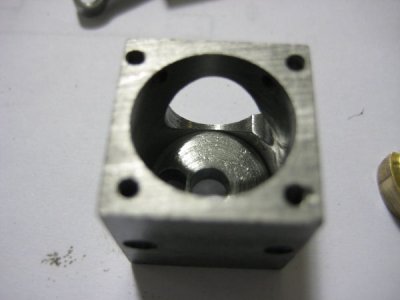
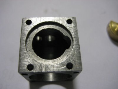
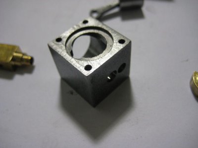
Clamping the piece in the mill with the top up, I located the center of the top surface (from the same corner the center of the cylinder was located from) and drilled a 7/16" hole about .4" deep. Then with a boring and finishing head I made the .035" recess that accepts the cylinder. I tried to get as high quality of a finish as possible on this because I didn't plan on using a gasket between the cylinder and crank case. I cut it about a thousandth shallow so that I would be ensured a nice tight fit between the two mating pieces. Using the same measurement as the cylinder, and the same technique I cut the transfer port into the crankcase. Since the piece was located I went ahead and tapped the four 2-56 holes on the top.
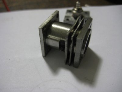
Turning the piece so that the front faced up I located the top right corner with a edge finder then counted off to the center. I drilled out the crank case up to 1/2" about .020 shy of the required depth of .613" then using a boring and finishing tool I brought the hole up to .6" and finished the inside surface that the rotary valve mates against. There are two tricky things to this hole: getting the depth is important so that there isn't much play in the stack (valve, con-rod, crankshaft) once it is assembled, and that the back surface of the hole is a planar with as high quality surface finish as possible so that good seal is obtained between the valve and the crank case. Next I drilled the holes for the intake and rotary valve in the back of the crank case. Since I had the piece located I also went ahead and drilled and tapped the four 2-56 holes in the front of the case, noting which corner I measured from so that I could measure from the same one when making the crank seal.
Flipping the case over I located one of the corners using a edge finder then drilled and tapped the two holes on the bottom used for mounting the engine to a stand.
Crank Case Seal
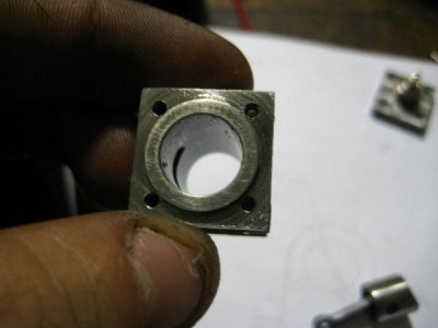
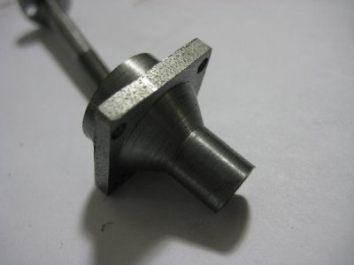
I don't really know what the correct name for this part is, since it seals the front of the crank case I call it the crank case seal. I started with a 3" piece of 3/4" square 1018 steel. I centered it in the four jaw chuck then mounted a tool bit with plenty of rake and clearance into the tool post. I set the angle for the taper cut to 30.9 degrees with respect to the normal of the 4 jaw chuck. Taking light passes until I had the shape I needed. The geometric accuracy of the taper isn't critical at all, and it would be okay to do it by eye, in fact the taper is more for show than anything else so to completely forgo it would be completely acceptable. I took the piece out of the chuck and in the horizontal bandsaw cut it down to apprixmately.72" in length.
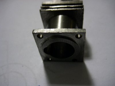
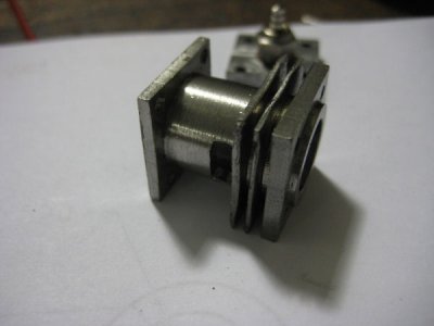
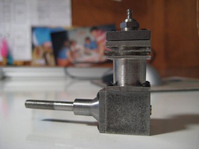
After cutting it down to length, I turned the piece around and mounted the .30 inch section in a 19/64" collet and turned it down to length. After that I turned down the .6" diameter section on the back. Next I drilled and reamed the .1885" through hole. One important part that I didn't note in my drawings is to make a small step around the .1885 hole to reduce friction of the crankshaft against the seal (this can be seen in the images below).
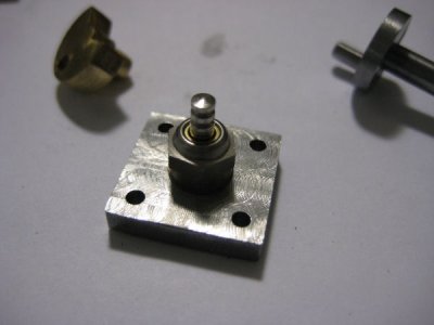
Moving to the mill I located in the top right corner (same corner I measured from for the crank case) using a edge finder and drilled the .086" holes for the bolts. And with that the part was done.
Cylinder Head
At this point I was no longer trying to figure out which parts we're hardest, I decided I wanted to make all of the external parts first then the internal parts second. The final external part to make was the cylinder head.
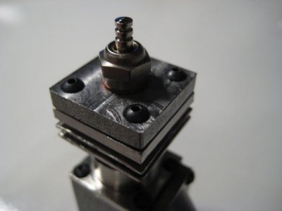
Starting with a 3" piece of 3/4" square 1018 steel centered in a four jaw chuck I faced the end, then, using a tool bit with a lot of rake and clearance cut the recess for the head gasket.
Then in the horizontal bandsaw I cut the piece off with about .030 extra length. Taking it over to the mill I mounted it on the highest parallels and using a 1/2" end mill I milled it to the correct height.
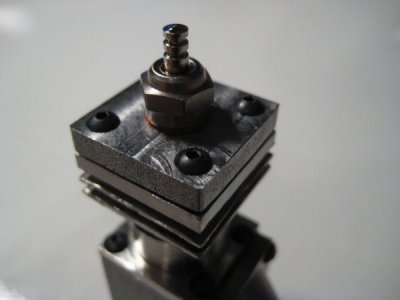
Locating a corner using the edge finder I drilled the four clearance holes for the head bolts then drilled and tapped the 1/4-32 hole for the glow plug. With that the cylinder head was done.
Crank Shaft
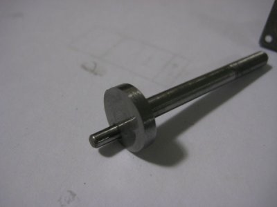
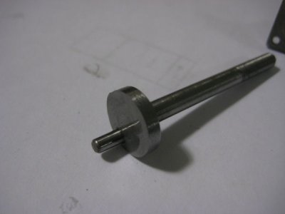
With the external parts finished, it was time to make the inside ones. For no particular reason I decided to make the crank shaft first. The crankshaft was designed to be as simple as possible, being three very simple pieces pressed together.
The first piece is a .125" diameter pin. The one that I used was pre made but one could easily be made from drill rod.
The second piece was a 2 inch length of .1885 drill rod. To make it I cut the piece to length then mounted it in a collet to face the end. While it was still in the collet, I threaded it 10-32 for about 1" along its length. This was to give me the flexibility to mount a propeller in the future if I wanted.
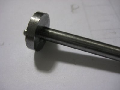
The third piece was made from 1018 steel bar turned down to .55" diameter. While it was still in the chuck I drilled and reamed the center hole for a press fit. After that I parted it off about 10 thousandths too thick. I call this piece "the disc" in the next step.
In an arbor press I pressed the disc and .1885 drill rod together with the rougher side from parting facing away from the drill rod. I then mounted the drill rod in a collet with the disc facing out and faced off the 10 thousandths I left on when parting it.
Moving to the mill I clamped the assembly vertically in notched parallels with the disc sticking out the top. Using a dial indicator I centered it in the mill then counted off the distance the pin, then drilled and reamed the hole for it. Going back to the arbor press I pressed in the pin. With that the crankshaft was complete.
Rotary Valve
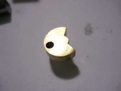
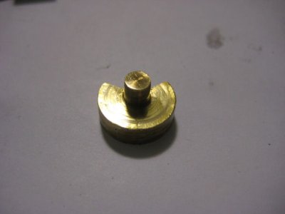
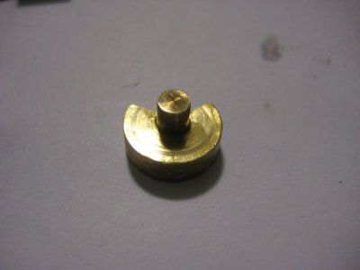
Since the rotary valve was connected to the crank shaft, I decided to make it next. I actually started with a brass door knob, turning it down to a .55" cylinder. This is differs from my plans which call for a steel rotary valve. After turning it down to the correct diameter mounted the newly made cylinder in a three jaw chuck and turned down the .125" shaft coming out of it, making sure to get the inner surface as high of quality of possible in order to obtain a good seal against the back of the crank case. After that I parted it off taking my time to get a high quality surface finish.
Moving to the mill I mounted it in a collet block and indicated the mill to the center of the piece. I counted off to the hole for the crankshaft pin then drilled and reamed it.
To get the angle in the valve I very very carefully did it by eye in the mill. I couldn't explain how I did it, and I know that it was very bad technique, so I am not even going to try.
Piston
The piston had my stumped for a while, in my research I read that the best material to make it out of was cast iron. I couldn't seem to find a source of cast iron anywhere. Finally when scrounging through my garage looking for parts I found a dumbbell. I had the realization that they are made out of cast iron and even though I was afraid that it would be porous or included took it into the shop to attempt to fashion into a piston.
I started by cutting the thick ends off of the dumbbell in the horizontal bandsaw. Then, mounting the left over middle piece in a three jaw chuck I turned down the end to .4377" I knew I would need to lap the end so I didn't part it off yet.
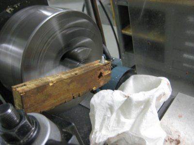
I made a lap by drilling a 7/16" hole through a piece of scrap wood, slitting it, then putting in a bolt so I could tighten it. (see image)
Lacking lapping compound and wanting to get on with the project I used automotive rubbing compound. It does work, but I strongly advise against it as it is excruciatingly slow. Using the setup in the above image I lapped it down to .4375" then cut it off in a horizontal bandsaw.
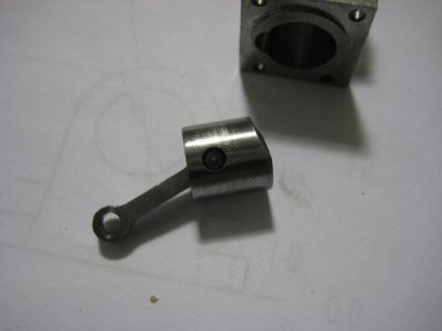
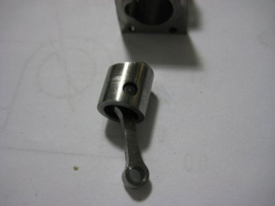
Mounting it in a 7/16" collet I used a 1/2" endmill to face the cut end and bring it to .4" length. Using a dial indicator I indicated the mill to the center of it and drilled the .313" hole in the bottom, then switching to a countersink bit made the 45 degree chamfer in the bottom hole, the angle isn't critical, any normal countersink bit would work. Changing orientation of the part, and locating off the bottom surface and side of the piston, I drilled and reamed the .125" hole for the wrist pin.
Turning the piston around in the collet and ensuring that the the hole for the wrist pin was parallel to the z axis, I located the top and side of the piston using a edge finder then cut the notch in the top using a 1/2" endmill.
Connection Rod (conrod)
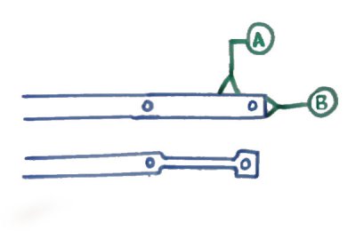
The conrod was made out of a pice of .125" by .25" cold roll steel. I started by clamping a foot long piece on parallels, with the .25" side facing up in the mill with about .8" overhanging from the right side of the vice. I faced off the end to get it nice and square, then located off face A and B in the illustration below. Counting off to the location of the first hole I set that as my zero. The locations of the side slots are dimensioned from this hole so it is very convenient. I drilled and reamed the two holes, then mounting a 1/4" endmill, I milled out the two reliefs on the side of the conrod. Since the piece I was milling was overhanging over the edge, quite thin, and not very well supported, I took very light passes to keep the forces on it low. Removing the piece from the mill,I left the piece connected to the long parent piece to make the next step easier.
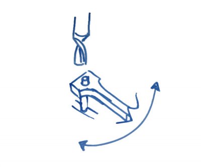
Making the profiled ends of the conrod was a whole lot easier than I had anticipated. Originally I had planned on using a rotary table to get the round profiled ends, but setting it up for a piece as small as the conrod would have been a nightmare. I read somewhere that people would mount the conrod on a pin by one of the through holes on the ends (which are conveniently concentric to the profiled end) then turn it against an endmill to get the round shape. (see my illustration below)
Once the first end is profiled, I cut the piece off in the bandsaw and mounted the other end in the pin. Holding it with a pair of pliers I profiled the other end, remembering they are both the same radius.
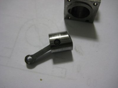
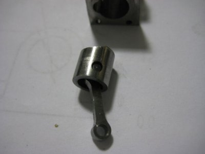
The final step was to make the wrist pin. I cut a piece of .125" drill rod to about .010" less than 7/16". Mounting it in a collet, I used a file to give the ends a spherical profile. The wrist pin is a sliding fit, the profiled ends are so that it doesn't gouge the cylinder walls.
Lapping The Cylinder
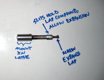
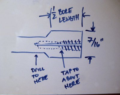
There are two reasons why the cylinder needs to be lapped, the first is to give it a good finish and very cylindrical in shape the second is that in engines without piston rings a slight taper to the bore is desirable so that a very tight fit is obtained near top dead center where compression is maximum. In order to obtain this an expanding lap had to be made. I ended up making the lap below. It has a slitted head with a hole tapped in the center using a taper tap. As the screw hits the tapered section of threads it expands the lap. The lap is a piece of aluminum turned down to the required shape pretty much by eye. The only three important measurements were that the "head" of the lap (the slitted part) was about half the length of the bore, that the diameter of the "head" was 7/16" and that hole wasn't tapped too deep. (see illustration)
After I had turned the piece down to the shape that I wanted, I drilled and tapped the hole for the 10-32 screw. I tapped it so that that there was about 3 complete threads formed before the tapered section.
Going over to the mill I slitted it using a slitting saw. It was important to slit past the head into the neck so that the head could expand uniformly.
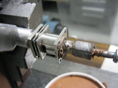
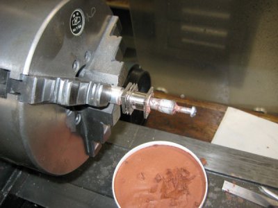
Now that the lap was done, I mounted it in the lathe by the thick part on the back, put the screw in finger tight, and loaded the lap with lapping compound and a drop of oil. I set the lathe at about 100RPM. Before I started the lathe I put the cylinder on the lap. The cylinder sits on the thin neck of the lap with the bottom facing away from the lathe chuck (see image below). When the lathe is turned on, the cylinder is slowly pulled (by hand) over the "head" of the lap stopping just when the head of the lap emerges from the top of the cylinder. The piston is stroked up and down on the lap until resistance drops to zero. Once the resistance drops it means that the lap/cylinder has been worn down and the lap needs to be expanded. Every time the resistance would drop, I would remove the cylinder, clean it thoroughly, put it back in the lap, expand the lap by turning the screw about 1/8 of a turn, reload it with compound and repeat the process until the piston would slide in easily to the exhaust port and would go the rest of the way with some resistance but not catching or sticking.
Needle Valve
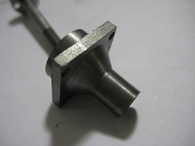
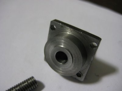
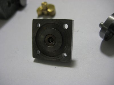
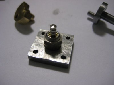
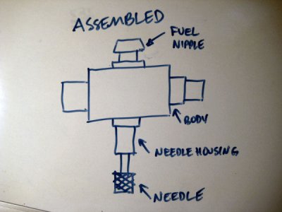
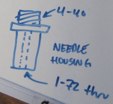
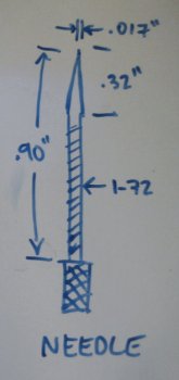
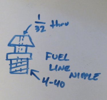
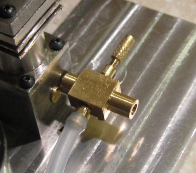
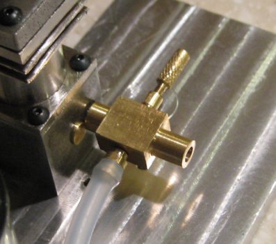
The needle valve for this engine I made very quickly without any real plans. It is made entirely of brass and is quite simple to make compared to the engine so I won't go into detail. The illustrations below should explain it fully. All critical dimensions are dimensioned. Everything else I just did by eye.
Assembly and Testing
Assembling the engine was straightforward. I put castor oil on every part before putting them together. My plans called for socket head cap screws, but I couldn't find anywhere that actually had them so I ended up getting button head fasteners. I assembled the engine completely except for the head. Turning the piston to top dead center I measured how much space there was between the top of the piston and the top of the cylinder using calipers. It ended up being about 25 thousandths too high (I actually worked this into the plans to allow for different gasket thicknesses and to absorb any error in construction) so I took it over to the mill and shaved off the 25 thousands with a 1/2" endmill. After thoroughly cleaning the cylinder I bolted it back onto the crank case. I also still needed to make the head gasket so I got some aluminum foil and cut it out by hand with an exacto knife. I made three layers, sandwiched them between the head and the cylinder then bolted it down tight.
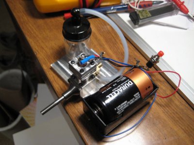
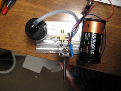
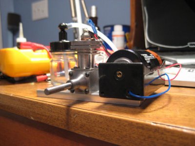
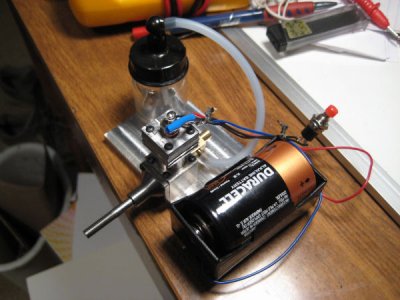
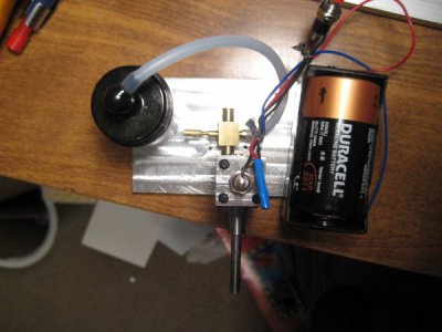
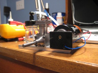
To make a base for the engine, I drilled and countersunk two holes in a piece of scrap aluminum plate to match the tapped holes on the bottom of the crank case. The fuel tank was made from an old airbrush paint canister simply because of its convenient size. I put a 6" length of silicon fuel tubing from the fuel tank to the needle valve and filled the tank with a 30% nitro fuel mixed 2 parts fuel 1 part castor oil.
In order to power the glow plug I connected a "D" cell battery to by wrapping the wires around the plug, with a PBNO push button in the line for convenience. (see images)
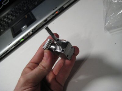
I put the counterweight from my air engine on the crankshaft and a small plastic washer from a sink to create a makeshift slot for a pull-start. (see images). Clamping the engine to my porch railing, it was ready to be tested. I screwed the needle valve shut then backed it out about 2 turns, this is where my engine ran best. After about 20 tries the engine sputtered to life running for about 5 seconds. Subsequent runnings couldn't get the engine to run for more than 20 seconds. I could see fuel/oil bubbling from between the head and the cylinder. Doing some research showed that leaky head gaskets can cause the same problem I was having. I haven't tried fixing it just yet, but I will and post my results as soon as I do. Be sure to check out the gallery to see a video of it running!

