
My goal is to make a CNC mill that is as autonomous as possible. Ideally spitting out parts for me without having to touch it (unlikely). One challenge on the road to that goal is for the mill to be able to automatically switch tools for different types of cutting operations. Before I can even consider building an automatic tool changer I need for my mill to be able to selectively grab and release tools which is a project unto itself. I'll get into the details below, but to avoid burying the lede, this is what I'll be discussing:
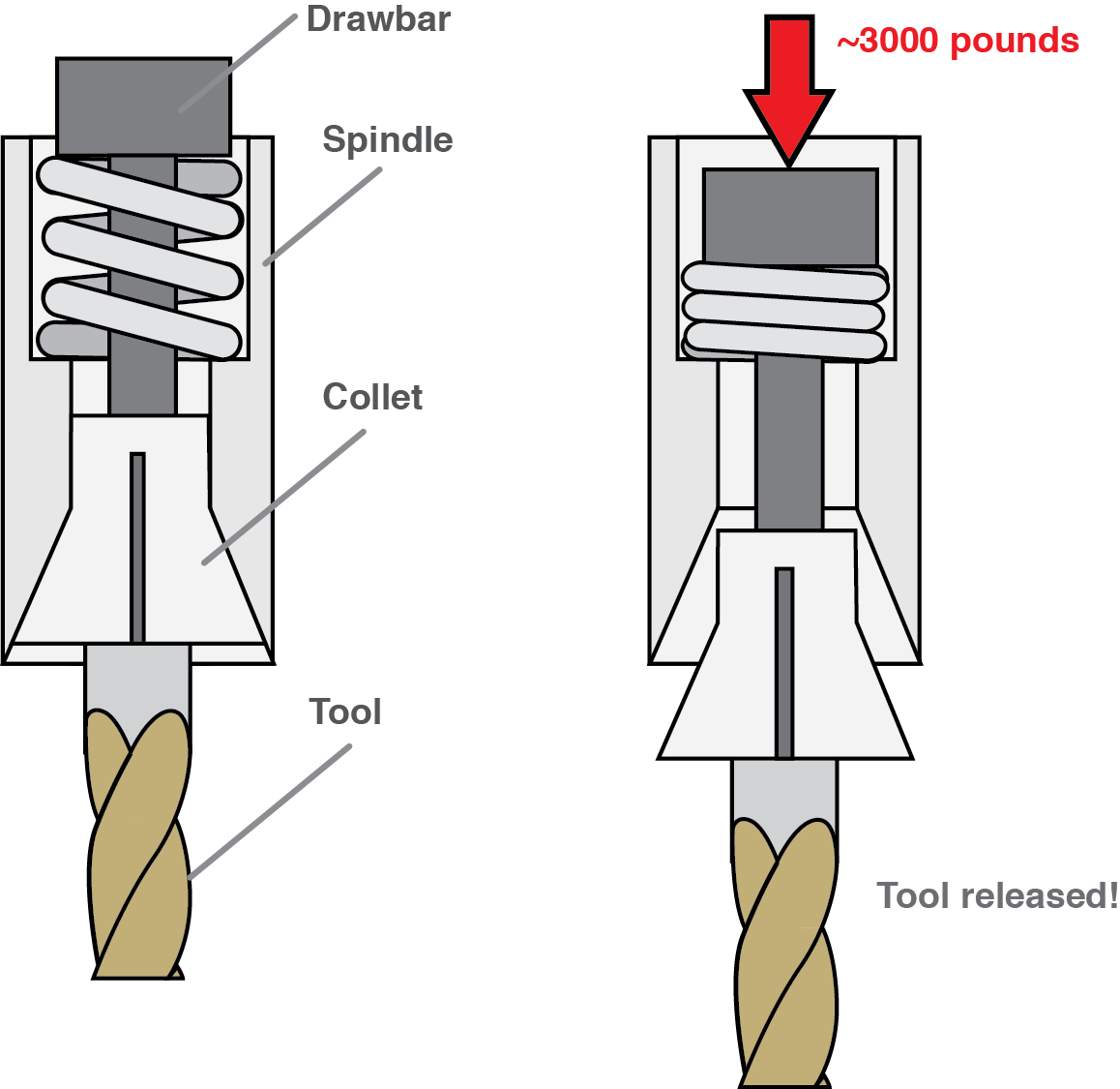
Many manual mills hold tools with a tensioned rod pulling a collet which clamps onto the shaft of a tool. When I started to do research for this project I was somewhat surprised to find that the tension in the rod is around three thousand pounds of force. If you want to make an automatic drawbar you have to find a way to selectively pull on a rod with over a ton of force.
This problem is already solved with two main options. You can turn a screw, which is a common way for drawbars to be manually actuated or you can put a really strong spring in series with the drawbar that preloads it so that it is always tensioned. To release tools you push on the spring hard enough to break the preload. Both methods have pros and cons, but ultimately I went with the preload method because it is easier to do quietly in an apartment as there is no pneumatic impact wrench, and it seemed easer to do reliably and automatically. If all that text isn't clear, here's how I wanted it to work.
The crux of the design is finding a reliable way to selectively apply around 3000 pounds of force to the drawbar. There are two main challenges with doing this:
- That's a lot of force without resorting to hydraulics
- You cannot apply the force directly to the spindle without damaging the spindle bearings
Challenge #1 - That's a lot of force
I ruled out hydraulics early because I really didn't want to deal with them. In my mind that left (in decreasing order of preference): pneumatic, some kind of uber geared down electric motor / linear acuator, or something exotic like a shape memory alloy acutator or a giant wax motor. I decided to go with pneumatic for two reasons:
- It's what pretty much everyone else does. There is usually wisdom in the crowd.
- Assuming nominal gearbox losses it would take somewhere between 0.5 - 1 horsepower to give a 1 second actuation. The mill spindle has a 0.6 horsepower motor. No thanks.
My first thought was to put a pneumatic cylinder in line with the spindle and press on it directly.
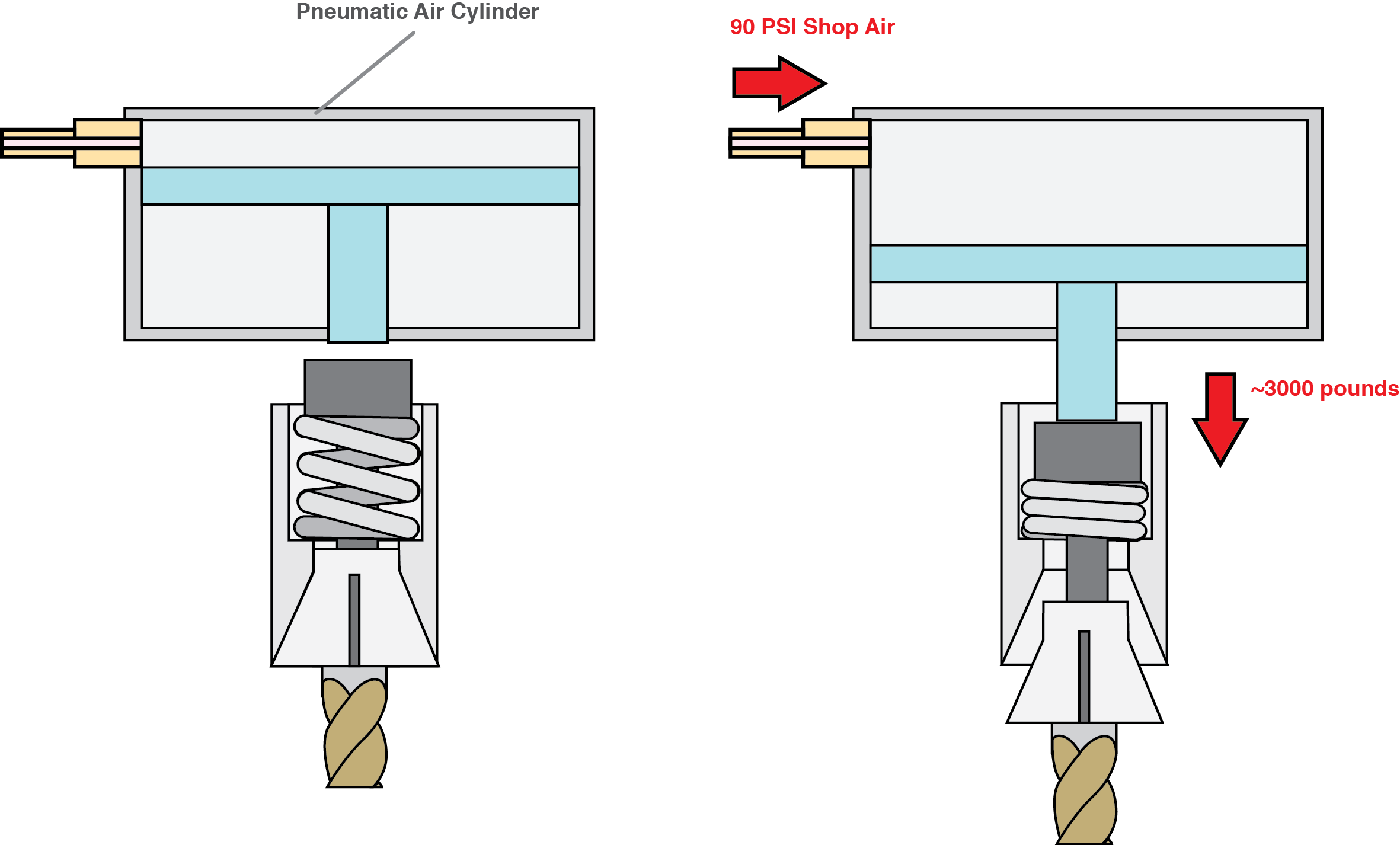
Although this would be easy to build, back of the envelope calculations show that the air cylinder would need to be at least 6.5" in diameter to generate the required force That is both a huge and expensive air cylinder. You can get the air cylinder size down by using multiple smaller air cylinders in parallel. This is known as a "multi-stage air cylinder" and is what the tormach does for its power drawbar. I was tempted to just do this and call it a day but it would have been a relatively expensive (~$500) USA made semi-custom air cylinder, build my own, or a long wait from China via Alibaba. Between tooling and material cost it didn't make sense to make my own, and Alibaba wouldn't have cut it because I wanted a power drawbar now.
The saving grace for this problem is that the high force only needs to be applied over a relatively short distance. Taking into account all of the tolerances I estimated that I would need about a half inch stroke. This means that a smaller force air cylinder with a long stroke can have its force multiplied with some kind of lever. This is a great solution in principle, and there are serveral designs based on it floating around the net. The only reason I didn't go down this path is that I couldn't find a configuration that I really liked on terms of comapctness.
Thinking about simple ways to amplify force there is another obvious way to do it. This is so obvious I am surprised that I have never seen anything like it before: use a wedge.
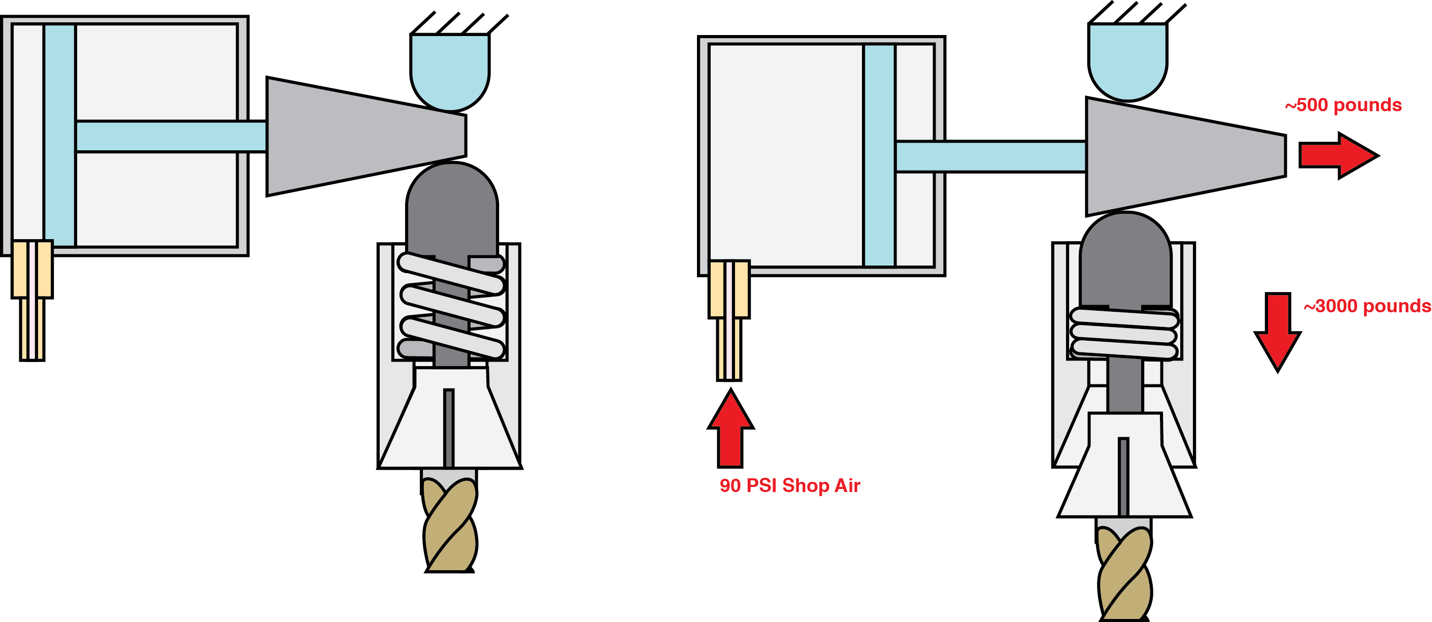
I really like the novelty and elegance of the wedge so it is what I ultimately went with for my design. The only real downside to the design is that it is a bit more complicated mechanically than a simple lever, though it packages really nicely. The jury is still out on reliability but I have done many thousands of tool changes without any issues so far.
Challenge #2 - Don't break the bearings
The spindle bearings are not rated for 3000 pounds of static axial loading so it is important not to subject them to that.
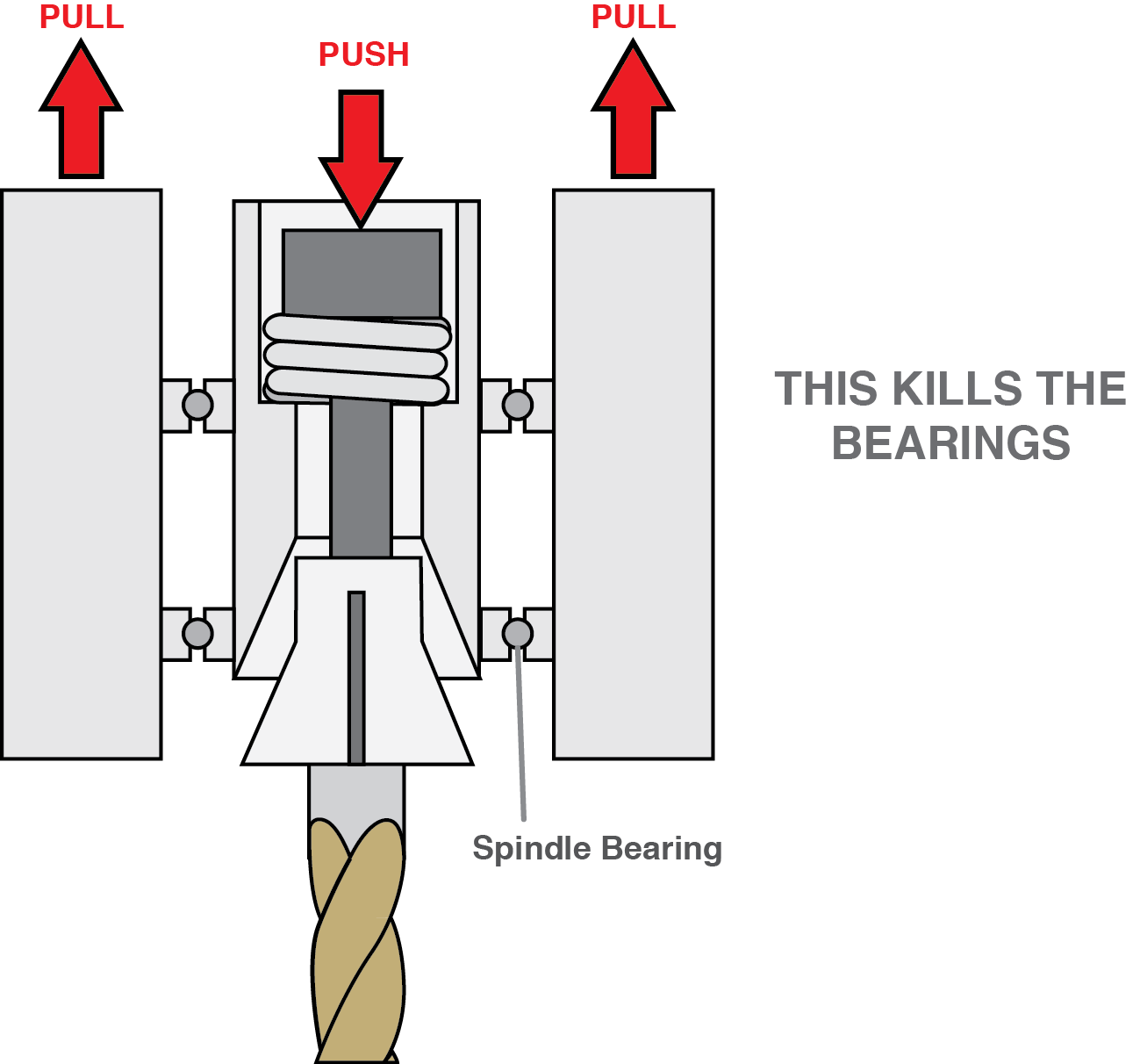
In principle this is not hard to avoid, you just pull against the spindle so the force does not go through the bearings. This is more of a practical challenge since you need to grab onto the spindle to pull against it, but you also don't want to touch the spindle when it is spinning.
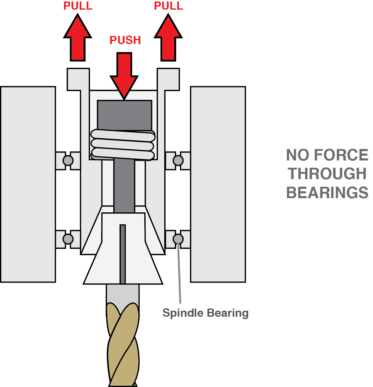
Theres a few ways you could imagine to solve this, the simplest solution which others have done before me is to have a flange built into the spindle that the drawbar pulls against with a gap so that the drawbar isn't touching when the spindle is moving. When you activate the drawabr it pulls itself up against the flange.
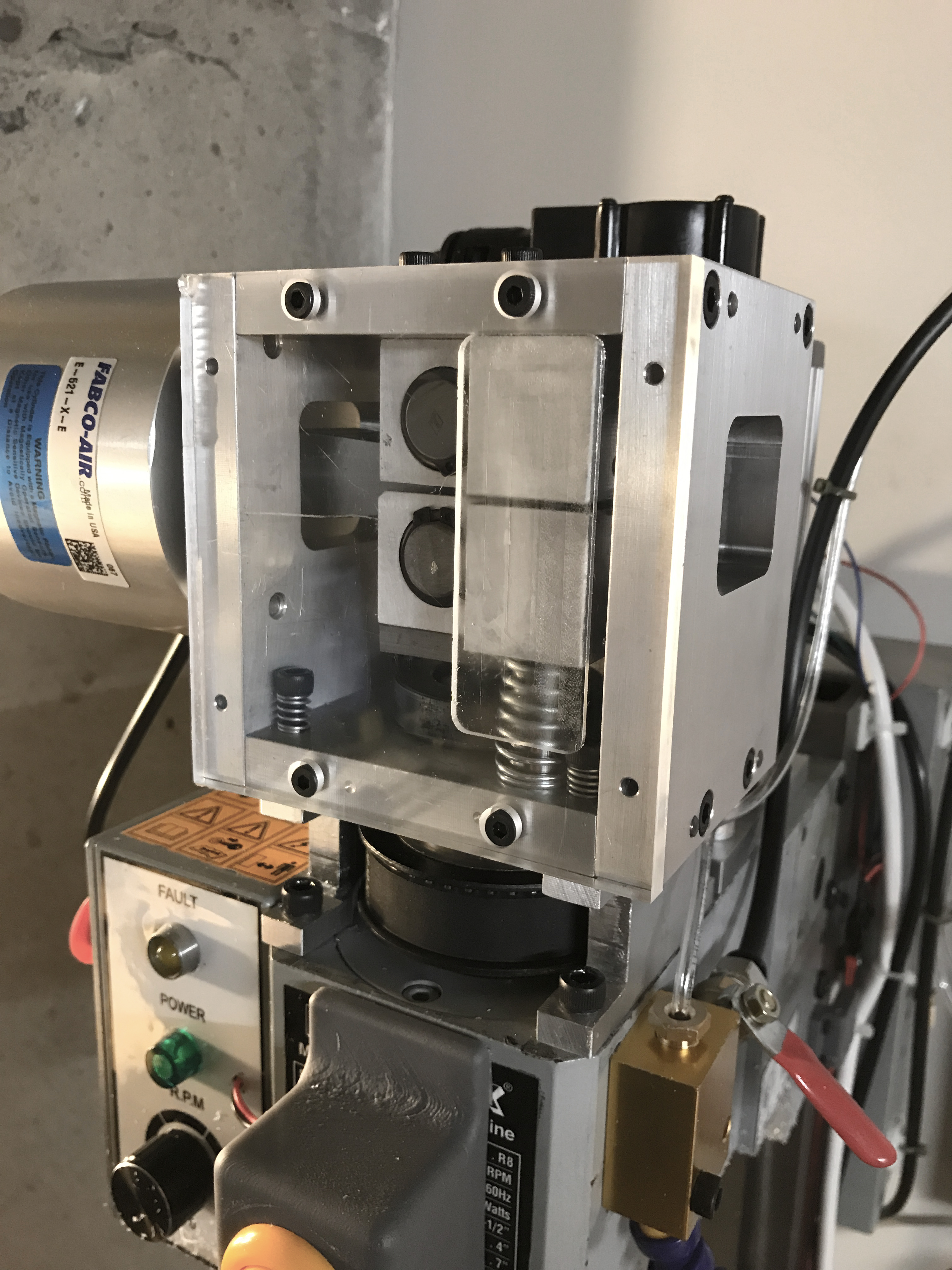
With the fundamental architecture questions answered, the remainder of the design and build centered around reasonable and reliable ways to build this contraption. I decided to use bronze bushings for the linear action with needle bearing supported shafts riding against the wedge. Compression springs ensure that the anvil retracts from the drawbar, as well as smaller springs which ensure the whole assembly retracts from the spindle correctly and seats correctly on its mounts. Both the bushings and the bearings are press fit.
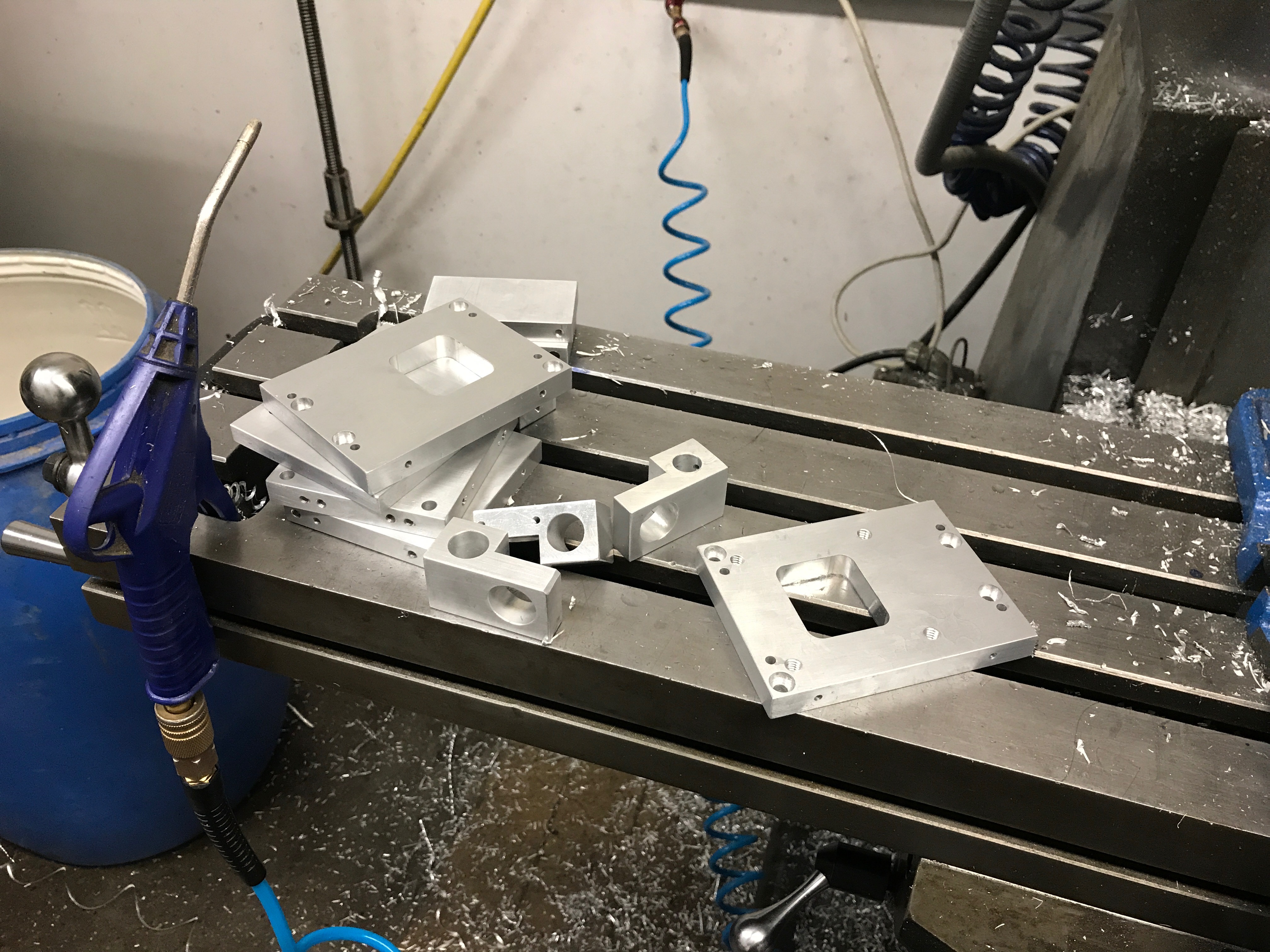
All of the parts save a select few which I made on the mini-mill were made on a manual mill / lathe so most parts were designed to be easily made out of 1/2" plate or 1.5" bar stock. Aside from ease of manufacture, I also did this to reduce material cost.
There are a few steel parts in the assembly:
- Wedge
- Rollers
- "Anvil" (part that presses against the drawbar)
- The "Cup" which holds the springs and the drawbar pulls against.
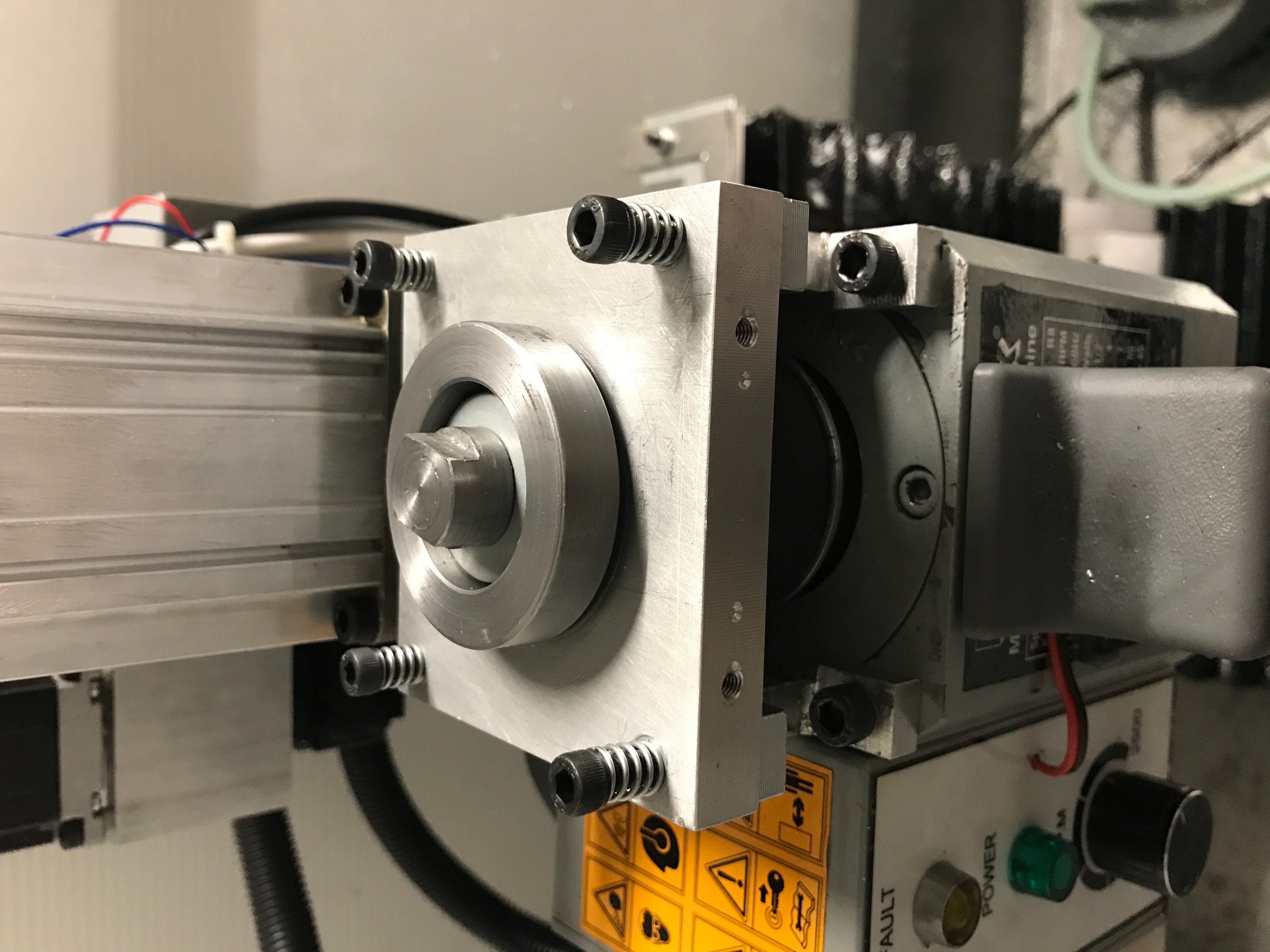
Here you can see the stage that the entire head sits on with the drawbar and springs inside the "cup." The springs are a stack of eight belleville washers in series to get the desired force and displacement. I actually had a hard time sourcing suitable washers and ended up ordering spare belleville springs used on a tormach.
The whole thing is actuated with an electric solenoid valve. A really important addition is the adjustable resistors on the exhaust. Without them the action of the air cylinder is extremely fast & rough which likely would damage the mechanism.
This hopefully gives you a good overview of the drawbar and highlights the interesting aspects of the build. If there is any interest I can potentially share plans or model files. The only reason I'm not posting them now is that I did this whole project start to finish in about a week and as such they are pretty rough. Hopefully if you got this far you found it interesting!