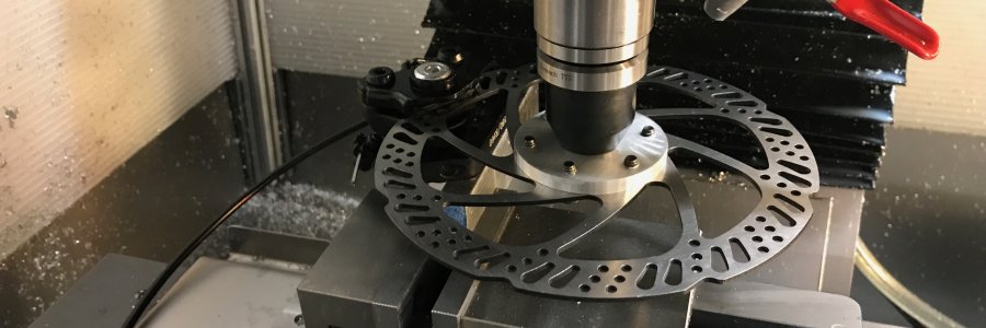
My CNC mill is tiny. It is not very stiff, it can't spin tools very fast, and the spindle motor is a paltry 500W (~0.6HP). It's certainly fun, but these shortcomings become major limiters whenever I try to push the limits and remove a lot of material fast. My quest to probe the limits of what my mill can do has made it clear that I really need to know the relationship of actual mechanical power at the tool vs. RPMs vs. torque. RIP broken endmills. This post will detail my first half successful attempt at getting this data and building a really weird mill tool.
Pop quiz: which tool seems out of place? More on this shortly...
You might be wondering why I don't just look up the power / speed curves for my motor. Trust me I tried. The motor is a generic BLDC and I could only find unit-less marketing graphs for possibly that motor. My spindle bearings also have an alarmingly high preload which means that some unknown amount of the motor power goes into doing work on the bearings (i.e. making them hot). Based on some rough temperature vs. time measurements I estimated that I am losing more than 250W at 5K RPMs. If so that's ~50% of my peak motor power doing nothing but making my mill hot! I had to get to the bottom of this.
I started by purchasing an inexpensive wall power meter . Assuming it's not giving me nonsense, these are great and I wish I would have had one in the past. I highly recommend picking one up. Plugging the mill into this and running it with no load I can see how much power the mill draws at different RPMs. As expected the power grows linearly with speed but seems even worse than I thought with the mill drawing >300W at no load.

Preload losses are normal, but this seems really out of whack. One thing at a time though - I wanted to finish understanding the power / speed curve for my motor. Phase two of my experiment involved loading the spindle until it stalled and seeing what power it was consuming. I can imagine a few ways to do this but I really liked the idea of just putting a bicycle brake in the spindle and pulling on that until it bogged down & stalled.
Would a bike disc brake work? My back of the envelope calcs show that stopping a 200lb cyclist going 20mph in 3 seconds requires over a kilowatt of braking power. I only needed around ~200W of braking power so as long as I wasn't riding the mill brake too long I figured things should be fine. The only difference between how I intended to use these brakes and a bike is that I would be turning the disc at 5000 RPM which would correspond to a bike going ~400mph. Let's just say I was glad to have my mill in a polycarbonate box.
The mounting is pretty simple - I machined an adapter which let me bolt the disc brake to a tool holder. I made a special nut which is held in the tool holder that the disc adapter screws into. Note that this specific configuration tightens the screw when braking. If this wasn't the case I would have wanted a secondary feature to prevent the brake from coming unscrewed.
The top of the disc adapter has a boss which locates it concentrically with the tool holder. This is important to minimize eccentricity and thus vibrations at the high speeds this thing is intended to run at. NOTE: the disc is installed upside-down in all these photos which means it is rotating backwards. That has since been fixed.
I also made a small adapter to hold the brake itself in the mill vise:
The final thing I built was extendo handles for the brake handle so that I would have more finesse and hopefully get better resolution in my measured stall power.
My technique was pretty simple:
- Let the mill warm up
- Measure the actual RPM of the spindle with a tachometer
- Ramp up braking until the spindle would bog down and stall
This worked really well until around 2500RPM when something popped in the motor controller. I have yet to debug exactly what gave up the ghost but this isn't all that surpising given the violent way that the motor was stalling with a big bang. My guess is that the motor controller was simply giving up and letting the motor rapidly decelerate and generate a big voltage spike which would understandably fry things.
I did manage to get some neat data up until the failure and draw some soft conclusions:
- The motor power increases with RPM at a similar rate to the preload losses which semi-cancels out to give a net power at thet tool of around 150-200W.
- I calculated torque from the RPMs and power. The motor seems to have good low end which drops off to a relatively consistent ~8in*lb
- This mill is wimpy and I need to fix the power at the tool situation.

