
I have been having a lot of fun with an iPhone game called tilt to live. The game is relatively simple to play - you steer a ship around the screen by tilting the phone. You are trying to avoid enemies, pick up power-ups which you can use to kill enimies. It seemed like the type of game that a program could do very well at if you cive a computer the ability to tilt the phone and see what is going on. In this project I built a motion platform which I hope can be used to get a really high score in this or other tilt based games.
The basic requirements for the platform are:
- Two controllable rotational degrees of freedom
- A vision system for image processing
There are a many configurations which will achieve the two degrees of rotation. Ultimately I decided to go with a gimbal setup. The final product under manual control can be seen in the video below (without the camera):
I decided to go with servos since I have some experience with them already. I filmed myself playing the game to get an idea of required rotation speeds / accelerations. Some basic dynamic analysis led me to the MG996R servos which satisfied my torque and speed requirements.

I designed the platform around the servos going with a single gimble ring and one servo riding under the phone. I am pretty happy with the configuration.

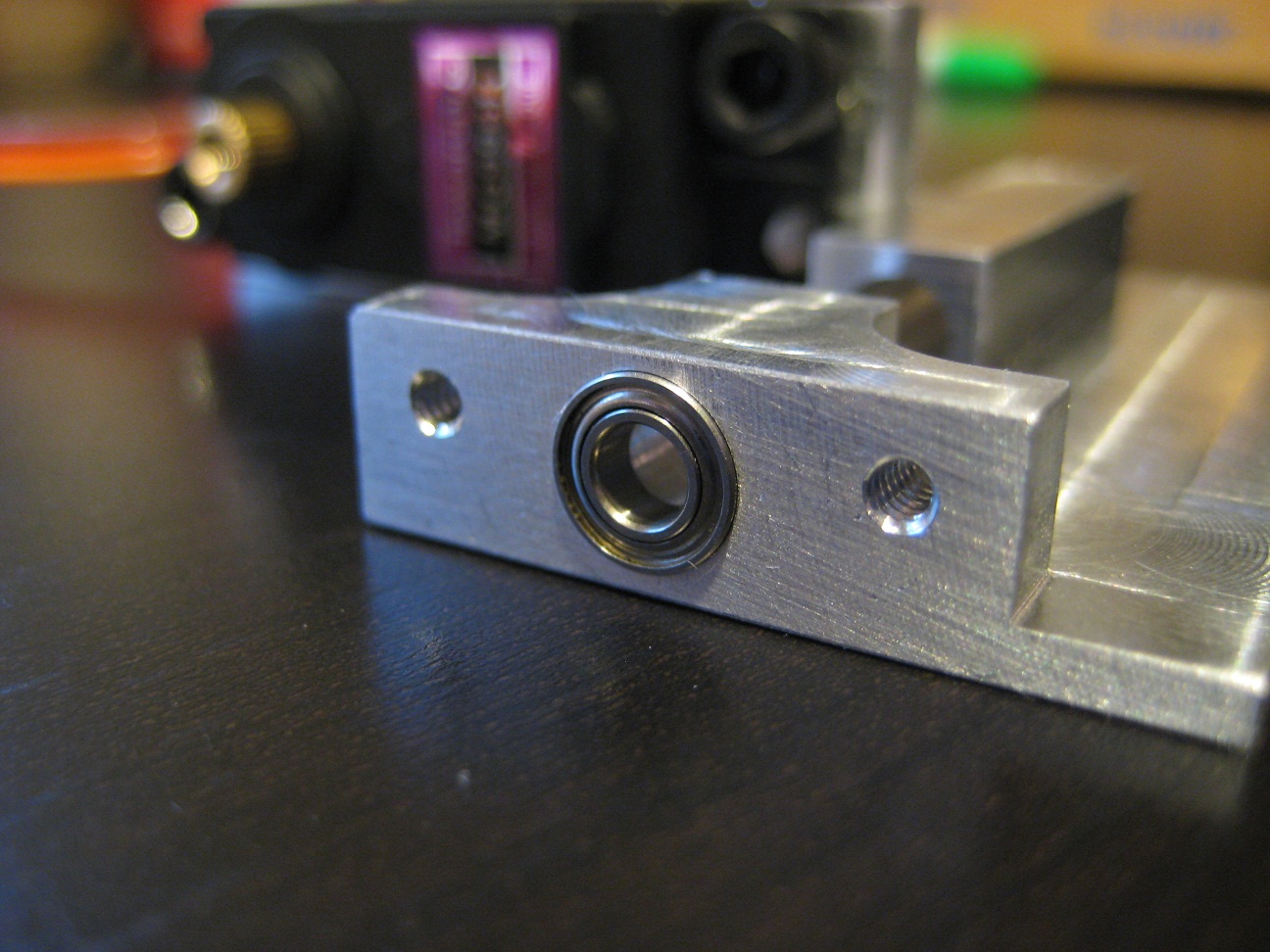
I optimized the mechanics for low rotational mass and low slop. This resulted in some relatively complicated parts to machine.

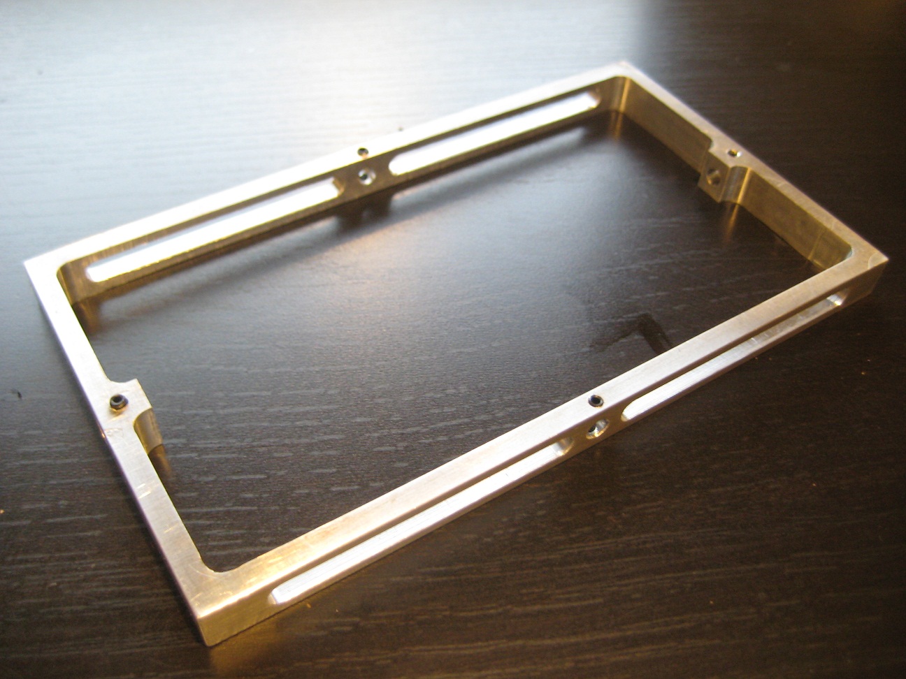

All pivots are bearing supported. It was amazing how expensive small bearings are. Ultimately the best source I found was bearings for RC helicoptors.

The servos are connected to the gimbal with ball joints, also from RC helicotors. They have very little slop and are easy to fine tune.


The phone is mounted in a cheap monoprice iPhone case held on to the structure with 3M VHB tape. It isn't going anywhere.


Finally, choosing and mounting the camera was surprisingly difficult. I purchased several until I found an inexpensive logitech camera that had a manual focus which could focus on something 4 inches away and had a mounting system that could be adapted without too much hacking.


There is still much to do. Currently, the robot has a manual control mode using a simple joystick, and a serial control mode. In both cases an arduino recieves input and moves the servos accordingly.


I have a very basic labyrinth playing program which will extract the walls and ball location from the camera images, solve the maze using the A* algorithm, then steer the ball along the desired path using a slow and basic PID control system. It's coarse, goes unstable, and generally needs a lot of work. Camera and servo latency are a concern but I'm happy to have a solid motion platform to build and improve on.